Caroline Klatman
Structural Option
181 Fremont
Caroline Klatman 181 Fremont |
| Building Statistics |
| General Building Data |
| Building name: | 181 Fremont |
| Location and site: | 181 Fremont, San Francisco, CA |
| Building occupant name: | Not yet occupied |
| Function types: | Mixed-use office and residential |
| Size: | 411,000 sq. ft. |
| Number of stories above grade: | 54 |
| Dates of construction: | Nov. 12, 2013 - Early 2016 |
| Overall project cost: | $375 Million |
| Project delivery method: | Design-Bid-Build |
| Primary Project Team |
| Owner: | Jay Paul Company |
| General Contractor: | Level 10 Construction |
| Construction Manager: | Jay Paul Company |
| Architect: | Heller Manus Architects |
| Structural Engineer: | Arup |
| MEP: | Arup |
| Waterproofing Consultant: | Simpson Gumpertz & Heger |
| Geotechnical Engineer: | Langan |
| Sustainability Consultant: | Urban Fabrick |
| Parking: | Watry Design |
| Elevator Consultant: | VDA Associates |
| Major National Model Codes |
| 2010 California Building Code (Based on the 2009 IBC) |
| ACI 318-08 |
| ASCE 7-05 |
| ASCE 7-10 |
| 2010 California Fire Code |
| 2010 California Mechanical Code (Based on the 2009 Uniform Mechanical Code) |
| 2011 California Electrical Code |
| 2010 California Plumbing Code (Based on the 2009 Uniform Plumbing Code) |
| 2013 Building Energy Efficiency Standards |
| Architecture |
| At a total height of 802.5 feet, the high-rise will provide a sleek, angular addition to San Francisco’s downtown skyline (Image 1). Tilted windows will offer a unique overlapping texture in the façade, while the exposed framing will add structural transparency and contribute to the buildings unique imprint. 181 Fremont will offer both residential and office spaces, with the top 15 floors dedicated to the residential units. A two-story open air terrace on the 36th floor will be made available to residents and help to connect occupants with the surrounding views of the Bay area. Additionally, a relationship with the surroundings will be furthered by the 5th floor connection to the neighboring Transbay Transit Center’s rooftop park, which can be seen left of 181 Fremont in the image below. |
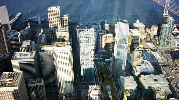 |
| Image 1 | Birds Eye View of 181 Fremont (At right) |
| Zoning |
| 181 Fremont is a mixed use building consisting of residential, office, retail, and parking uses. Zoning is in accordance with the San Francisco zoning standards for the C-3-O(SD) District – a special development Downtown Office. 700-S-2 is the height and bulk district classification. In addition to the requirements listed below, the project had to comply with the city’s requirement to either pay a housing development fee or provide more than 50,000 square feet of affordable housing in new office buildings. Additional Zoning Requirements: |
|
| » 3,208 square feet of open space | |
| » Maximum of 14,058 sq. ft. of commercial parking | |
| » 64 parking stalls for residential parking | |
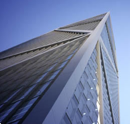 |
Building Enclosure A glass and aluminum curtain wall system comprises the exterior walls of 181 Fremont (Image 2). The typical roofing system will be comprised of an air and vapor barrier seal at roof edges, topped by insulation board. Substrate will be layered over the insulation, followed by adhesive to adhere the cover board. Above the cover board sill sit the feltback waterproofing membrane. To provide continuity in the waterproofing, the feltback membrane will be lapped over adjacent membrane and hot-air welded at material edges. |
| Image 2 | Upwards View of Facade |
| Sustainability Features |
| A curtain wall system that allows in ample daylight, thereby reducing the need for artificial lighting, will act as a primary sustainability feature for 181 Fremont. The curtain wall has a "saw-tooth" design which angles the glass mullions in a way that aims more glass area towards the north and east on each facade, and aims more solid mullion area towards the direct afternoon sunlight, thereby reducing the demand for cooling by over 6% (Image 3). Additionally, a green roof and use of recycled materials are planned to play a key part in the buildings construction as well. | 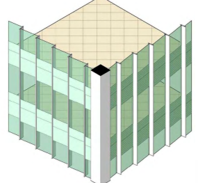 |
|
| Image 3 | "Saw-tooth" Curtain Wall |
||
Building Systems |
| Construction |
| After the demolition of two existing structures, construction for 181 Fremont broke ground in November 2013. Construction began with the installation of drilled shafts, including a 263 foot deep shaft deeper than any other in San Francisco. A partially cased polymer drilling method was used to reach 30 feet into "Franciscan Complex" - the name for the mix of shale and sandstone that can frequently be found in San Francisco. Shaft bearing capacity was determined using an Osterberg Load Test (O-cell test). Upon completion of the caisson drilling, basement excavation and construction began. The next phase of construction is the superstructure, scheduled to begin in November 2014. The superstructure will employ the use of a 1,000 foot tall tower luffing crane that is able to carry loads of over 40,000 pounds vertically at a speed of 623 feet per minute. A temporary construction elevator will be located in the interior of the building. Openings to allow for the elevator will be located on each floor, including basement levels, and will be filled at completion of construction. |
| Lighting |
The glass curtain wall system, paired with an open-office floor plan, provides a primary source of lighting during the day (Image 4). Minimum wattage light fixtures supplement the natural lighting, and motion-sensors mitigate unnecessary artificial lighting usage. Localized task lighting, as well, decreases excess usage. |
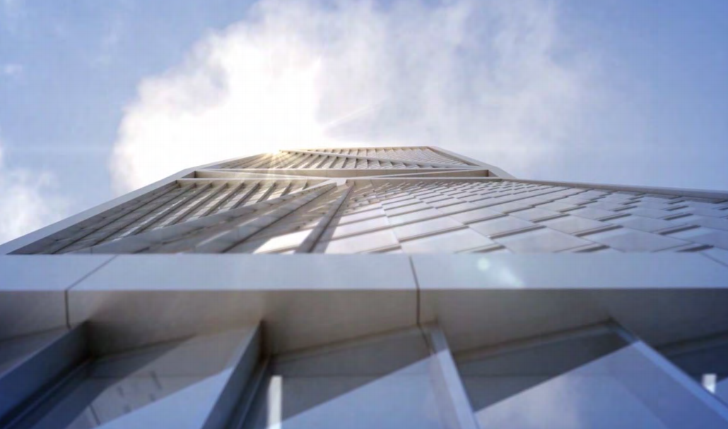 |
Image 4 | Upwards View of Curtain Wall |
| Mechanical |
| Mechanical space is provided in the basement and on levels 2, 37, 53, and 54, providing a total of 50,500 square feet in mechanical space. In addition to general mechanical equipment, slosh dampers are located on the upper mechanical levels to help counter building sway from lateral forces. Residential floors are serviced by a forced-air ventilation system, with intake air brought in on mechanical floor 37. There, the air is filtered and then transferred through ductwork to each residential unit where it is again filtered and then heated or cooled in a fan coil unit. |
| Structural System |
| 181 Fremont's Structural System consists of steel framing with a 3'-0" thick supporting mat foundation, 2'-6" thick basement walls, and five foot and six foot diameter drilled shafts to support core and exterior columns. Because the project site is atop an area of landfill that used to be affected by the bay, the soil bearing capacity is limited and shaft depths average 262 feet in order to reach into hard rock. 5 1/4" lightweight slab on deck is used on the office floors on the lower portion of the building, while the upper residential floors, beginning on level 39, have normal weight slab on deck for better acoustical performance. A typical interior bay is composed of W21x44's spaced just over 9' and W24x76 or W24x94 perimeter girders spanning about 19' and 30' respectively. The primary lateral force resisting system is an exterior mega frame, which is composed of vertical, horizontal, and diagonal steel members. Exterior steel moment frames surround the office floors to provide additional lateral force resistance, as do interior braced frames on the residential floors. Typical mega brace sizes on lower stories are 16x14x1.75x1.5 box shape hollow structural steel and lower story columns are typically 36x36x3c box shapes. Upper story braces, on the other hand, are W14x342 grade 65 wide flange steel shapes, while a common upper story mega column is a W14x233. Viscous dampers on the lateral bracing of the mega frame aid in reducing story drift and enhancing occupant comfort under wind loads. |
| Conveying |
| Thirteen elevators are provided for occupant use, including two residential elevators that service the residential amenities floor and residence floors, three elevators serving the high rise offices, three serving the mid rise office, four low rise elevators, and one service elevator serving every floor. Additionally, there is one elevator that spans between the B2 parking level and level 2. All elevators run on traction cables and serve as occupant evacuation elevators. |
| Fire Protection |
| Fire protection is classified as a life safety high rise over 75 feet, with type 1-A, fire resistive construction. Automatic sprinklers are provided throughout the building. Each exit stair contains class I wet combination standpipes with class III connections. |
|
|
AE Computer Labs Contact Caroline Resume |
|
|